
I was always a fan of the steampunk style, and having also had experience building steam engines in the past, there was only one real direction this project could go. Once I had my radiation detector kit hooked up to my Raspberry Pi running InfluxDB and Grafana, I found myself woodworking, machining, and fabricobbling an enclosure out of mahogany, brass, copper, toggle switches and, because it just had to be done, nixie tubes.
Read the story of the almost year-long journey (cough some other stuff cropped up…) I went on to make my steampunk vision a reality below, and if you want to get up and running quickly, find out how to build your own simple version right here!

Introduction
Low cost radiation monitors and Geiger counter kits have been available online for around \$30-50US/£25-45 for a while, but standing alone they don’t do much other than make the recognizable “clicking” sound we all know from movies and TV. I decided to up the ante by connecting one to a Raspberry Pi, storing the data with InfluxDB, and showing the readings with a Grafana dashboard.

The Grafana dashboard is accessible remotely via the balenaCloud public URL.
I updated the tech, gave it a web interface, added remote management, and built a custom mahogany housing with brass and copper fittings to show everything off, because it’s important to look suitably hip when sitting on the desk next to your train sign… right?

Anyway, I’m gonna show what I built to hopefully provide some inspiration, then show you how to get up and running with a simpler version of the project that anyone can build at home without any special tools. Let’s hit this.
Inspiration & design
I’ve always found the idea of radiation fascinating; how there are invisible particles moving around at incredibly high speeds, crashing into things and flipping bits all around us. Due to my fascination, it doesn’t take a lot to capture my interest when it comes to this field.
One day last year I was reminiscing over the now defunct UK-based electronics retailer Maplin, and how they sold all sorts of interesting kits for the aspiring engineer. This led me to Richard Mudhar’s blog where he tells the story of the Maplin Geiger Counter.

The original Maplin Geiger Counter. Perhaps some of the design cues are visible here?! (Credit: Richard Mudhar)
The kit that Richard has built above features both an electromechanical counter on the left, and two rings of LEDs reminiscent of dekatron tubes on the right. This display has the neat design feature that as the rate of count increases, the display becomes more noticeable.

The spinning light effect of the Dekatron is something I wanted to replicate. By Hellbus – Own work, CC BY-SA 3.0, https://commons.wikimedia.org/w/index.php?curid=4741470.
I liked the idea of combining the modern technology on the inside (Raspberry Pi, Grafana, etc.) with the timeless look of brass, copper, toggle switches, dark hardwood, and glass on the outside. The idea was now to build something that looked old and had that distinctive steampunk style, but was up to date and Internet-connected.
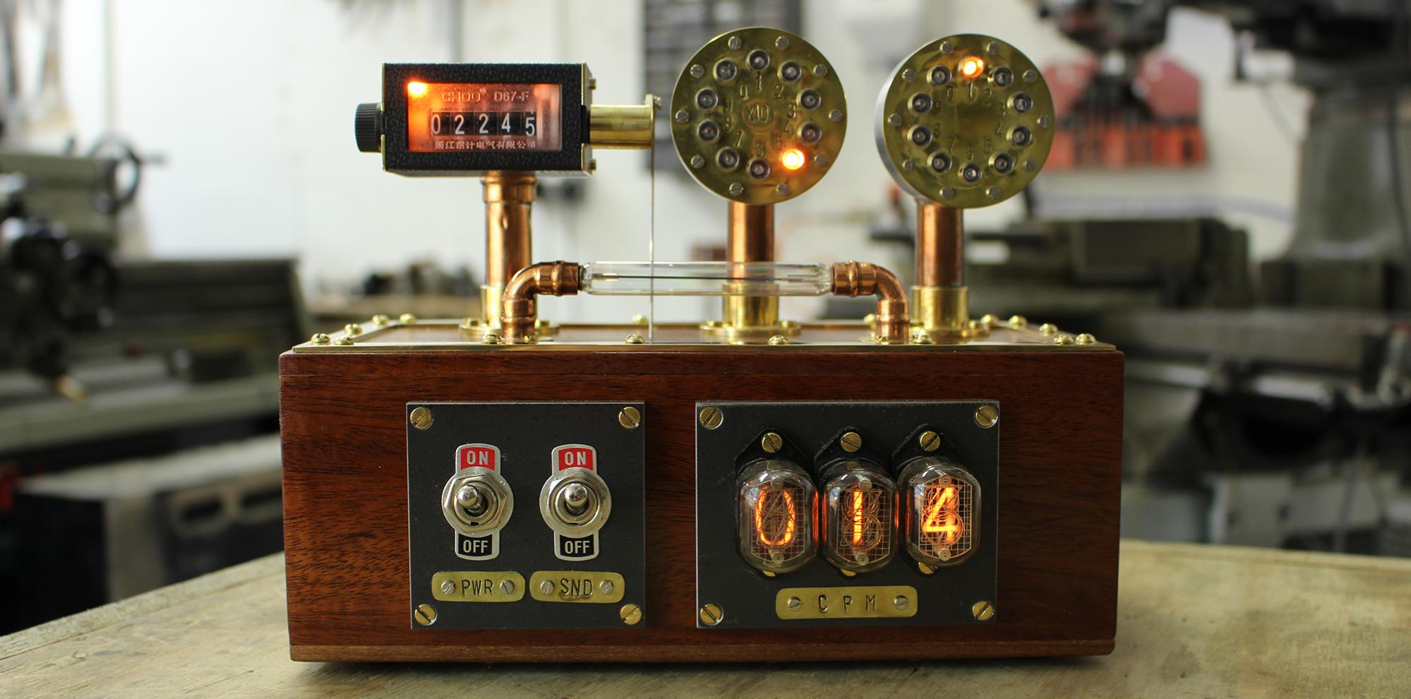
In addition to the total absolute count like the old Maplin counter, I wanted to offer a live display of the counts per minute (CPM) reading, and what better way to do this than with Nixie tubes, to get that nice warm orange glow and keep things looking cosy.
I started scribbling down ideas and thoughts of materials I wanted to use alongside shopping lists for parts, and possible designs for the case.

Notes don’t survive well in a machine shop, but these are what’s left of my original sketches.
This process was very much led by an image I had in my mind about how the thing should look and feel and so I just had to make it real… somehow.
The build
With some thoughts and ideas scribbled down it was time to get started. As this is for the most part going to be a bespoke, hand-built item, and made up as I go along, it’s not necessary to put everything in CAD. There are of course some core items that exist already and cannot change size; the Raspberry Pi and radiation detector board, for example. These are off-the-shelf parts that have to fit in the box no matter what, and start to dictate the size of the final unit.
Almost all other parts are completely hand made, machined and fabricated. This was necessitated by the desire to make everything authentic; I didn’t want to build things just for looks, I wanted any design choices made for aesthetic reasons to also be functional; by this I mean when I put 18 screws in something to make it look good, they are going to be 18 real screws that you have to take out to gain access!
NOTE: Each of the build log images link to a separate gallery when clicked. You can look through the images that way if you prefer, or read on in full detail.
The front panel
I started with the front panel of the housing, I knew I wanted two toggle switches; one for power and one for sound (to disable the clicking noise), along with 3 nixie tubes to display the CPM up to 999. Normal background radiation is in the range of about 25-75 CPM, so I figured if background radiation is above 999 CPM, we have bigger problems than worrying about enough digits on the counter.


The two front panel pieces are made from 6mm thick mild steel plate, cut to size with an angle grinder and then milled to dimension with the help of Bridget, the Bridgeport. Holes are then cut for the nixies and the toggle switches.


I manufactured labels for each by hand-punching lettering into 0.5mm thick brass sheet, polishing and fixing with M2 screws. The steel pieces are coated with a clear lacquer to prevent corrosion.
Working with wood
Wood isn’t my favourite material to work with, I mean it just changes shape of its own accord! Who can work with that?! Anyhow, it’s very pretty, and so it was decided that the outer box should be made of hardwood. I started with a scrap piece of mahogany, cut it to halve the thickness on the bandsaw, and then set about planing and shaping the sides of the box to fit the dimensions of the Raspberry Pi (3A+) and the radiation detector.


The dimensions of the front panel along with the steel faceplates were planned out in Fusion 360 so that I could print a cutting and drilling template. This was taped onto the planed piece of mahogany, the holes for screws were drilled, and the openings for components cut out.


The pieces were cut at 45 degree angles to enable a mitre joint in each corner. The joints were reinforced with biscuits (mmm biscuits), and then the 4 sides were glued and clamped and allowed to cure overnight.


The top and bottom of the case are made from the same scrap mahogany, but planed a lot thinner – approximately 6mm, the same as the steel plate.
Top brass
I had the idea that it would look good to hold the box together with a totally unnecessary amount of screws, 36 to be exact; 18 on top and 18 on the bottom. To prevent the screws damaging the wood surface and to add some extra detail to the top of the case I decided to make a brass plate that the screws all go through to clamp the top cover down.


Some pieces of 2mm brass strip were cut, mitred on the corners and soldered together. Once soldered, sanded and polished, the joints are barely visible.


Holes for screws were then drilled, and the brass plate used to secure the oversize lid to the box whilst it was sanded to size on a drum sander. I later learned that using a drum sander for this was a mistake as it marked the sides of the box, but you live and learn!

Finished case and lid woodwork with brass frame temporarily fitted
Imitation Dekatrons
My attempt at imitating the Dekatron tube effect starts with a piece of 50mm stainless steel (or aluminium) bar. The bar is turned on a lathe down to 40mm, and to have a cavity for the electronics. The work is removed from the lathe and parted off on a bandsaw before being returned to the lathe to have a hole drilled in the rear for cabling to drive the LEDs.


The part is then put on the milling machine to have 10 holes drilled and M2 ~~taps snapped off in the holes~~ threaded ready to fasten the faceplate.


The brass faceplate is made from the same 0.5mm thick brass sheet as the labels from the faceplates. Each piece is drilled with 20 holes (10 for LEDs, 10 for fasteners), and then hand stamped with the numbering for each LED.

The wired LED faceplate ready to be screwed into the housing.
The LEDs are wired with a common ground and connected using a piece of recycled floppy disk drive ribbon cable. All the work is then carried out a second time for the ‘X10’ display. The eagle-eyed readers will notice that the second display is made from a different material than the first – this is due to the fact I snapped both a drill bit and a tap off in the M2 holes – working with stainless steel with these small tools is very difficult! I ended up making the second from aluminium, which machines like butter, in comparison.
Fussy about fasteners
Throughout the development of this project I found myself continually swapping fasteners and trying different combinations to see what looks best. The end result is a mix of M2 and M3 metric machine screws in both brass and stainless steel, cheese head and countersunk head, all slotted. You may notice that in earlier photos some of the parts were assembled with Allen-head cap screws but these were later swapped out. Ebay is usually a great place to get small quantities of fasteners of all different shapes and sizes.

A mix of fastener types used for this project – various M3 and M2 machine screws.
The wood screws used for the top and bottom covers are 3mm brass button slot-head screws. Everything is polished on a polishing spindle with the help of a little holder.

A custom made M3 screw polishing tool 🙂
Plumbing in a Pi project
The copper parts you see in the project are made from standard plumbing supplies. I’ve used offcuts of 15mm pipe from the scrap bin, combined with a few elbows (both 15mm and 8mm) that I bought from a plumbing supplier. All of the brass parts in the project are custom made from bar stock to fit the application on the lathe.


Brass and copper parts are then soldered together using regular soft solder and a blowtorch in order to provide a rigid mounting both for the Dekatron displays and the mechanical counter.
Nixie tubes
The front panel has 3 nixie tubes in order to show the current background radiation CPM. Each nixie tube has a small backpack board with its own microcontroller; the Exixe by dekuNukem. These boards allow each tube to be individually controlled via SPI, and, although I’m not using them here, provide different effects such as smooth crossfading.

Pairing the Exixe boards with the nixie tube sockets. I tried to use spade terminals for this to make it modular but there wasn’t enough room.
The Exixe boards are designed to be mounted directly to the back of nixie tubes, but due to the thickness of the steel faceplate, and the use of socketed tubes (which I wanted to keep for both practicality in transport and aesthetic reasons), they could not be directly attached here. I extended the boards away from the back of the sockets on wires to allow them to pass through the opening in the wooden case and connect to the custom PCB behind which has the connection to the Raspberry Pi.

The Exixe boards connected to the sockets and to my custom backplane along with the 170VDC PSU.
In addition to the Exixe boards, nixie tubes also require a 170VDC power supply, which is provided from a 5V converter (available cheaply on eBay) and mounted to the custom board.
Electrifying a mechanical counter
I chose to use a mechanical counter for this project, specifically this one from Amazon UK. A standard servo is used to increment the count. As with many other choices, this was made purely for aesthetic reasons; although electromagnetic counters are available which simply require a pulse to increment them, they didn’t have the right appearance.

The stock mechanical counter as supplied.
Although the appearance was close to what I was looking for, it wasn’t quite right, and so some modifications were in order. A new backplate was made from aluminium and new side plates from 1mm thick brass sheet.


In addition, I also wanted the display to be illuminated with the same orange glow that the other components have. One orange LED (the same as in the counters) was fitted to the inside of the display, with the wiring routed out the back and down the copper pipe into the case.


A servo is mounted on the bottom cover of the case, and linked all the way up to the increment lever on the counter with a 1mm piece of piano wire. The servo is mounted using a 3D printed vertical mount.

Servo mounted on the bottom case cover.
A replacement link arm for the mechanical counter was made from a piece of round bar turned on the lathe to fit, and silver soldered to a flat bar before being shaped.


Electronics
The input to the project is of course generated by the radiation detector. This board generates a pulse for every ‘count’, which is then fed into custom circuitry to drive the LED displays, and simultaneously into the Raspberry Pi which allows us to drive the nixie tubes, the mechanical counter and log data in InfluxDB for use with Grafana.

Testing the electronics; the 4017 counter board for the LED displays on the left, and the Exixe backplane centre with other Exixe controllers on the right.
The two LED displays are driven via CMOS 4017 decade counters; these ICs receive the pulse from the radiation detector and drive 10 LEDs. The project uses two counters to be able to count from 0-100, after which the mechanical counter takes over.

Here’s the device schematic.
This setup could be improved; I originally had planned to design a 555 timer circuit to automatically trigger the mechanical counter servo when the second counter overflows. This would mean the 3 counters could work purely in electronics without the Pi. In the interests of getting the project finished, and due to lack of space to easily mount another board, I simply plugged the servo straight into the Pi. The downside of this is that when the count is very fast, some pulses that are recognized by the 4017s are missed by the Pi. Hopefully this is never an issue for a background monitor!
Relocating the Geiger tube
Whilst it isn’t the best idea for accuracy reasons, as the J305β tube used on this radiation detector can be sensitive to light, I wanted to relocate the tube to the outside of the box. Not only because it looks great, but also so that I can test items for radioactivity without the tube being shielded by the thick wooden case.


I turned two small brass flanges on the lathe, drilled them with clearance holes for M2 screws and soldered them to 90 degree 8mm copper elbows.


Wires were soldered to each end of the tube, and although it was almost a perfect fit in the 8mm elbows, I made small plastic sleeves to secure it and electrically insulate it from the copper.
Final assembly

All the parts for the project laid out ready for final assembly.
Power is brought into the case at the rear via a standard chassis mount DC jack, and routed via the PWR toggle switch to the custom board on the rear of the nixie tube drivers. From there it is distributed to all places that need it.

Ready to fit the bottom of the case, at last!
The buzzer was removed from the radiation detection board and remotely mounted via the SND toggle switch on the underside of the case lid, underneath a hole to allow the characteristic geiger counter ‘click’ to be heard.

The bottom of the case now fitted, along with excessive screws and rubber feet.
Finally, the bottom of the case is fitted along with the servo and the link connected to the mechanical counter control arm. You really do have to remove 19 (18 on the bottom and one on the counter control arm) screws to gain access to the Raspberry Pi in this build – I am glad to be using over the air updates with balenaCloud! 4 self-adhesive rubber feet were added, and the job is – finally – complete.

At last, the finished product ready to be powered on for the first time.
NOTE: To see it in action, check out our demo video.
Programming and software
The hardware is finished; what next? Aside from the fact that the Raspberry Pi is locked in a wooden box behind a lot of screws so I can no longer access it, the software for the project is very simple. I’ve published the application on GitHub.

Before the Pi was locked away I set up a balenaCloud application and flashed the SD card. This means that I can now remotely deploy updates to the Pi without fear of needing to take all the screws out every time I break the code.
balenaCloud gives me the facility to push Docker containers to the device completely remotely and provides a VPN connection with a public URL to the device so I can view the dashboard from anywhere.

Although it includes code for the Exixe Nixie tube drivers and the operation of the servo for the mechanical counter, this hardware isn’t necessary for the project to run, and at the simplest level it will still provide a dashboard and count the pulses from a connected radiation detector board.
To get started and try things out, click the deploy with balena button below, this will get you up and running with the application, then you can add a Raspberry Pi and radiation detector as a second step by downloading the OS image from the new app.
For more details take a look at the simple background radiation monitor build guide to find out how to assemble and set up your own version.
You have come to the end of your journey
Survival is everything. Thanks for following along to the end of my extensive build log. This has been a fairly long term project for me as progress was a bit sporadic and fit amongst many other priorities here at balena.
I encourage you to take a look at the simple background radiation monitor build guide to get started building your own, and am interested to see what cool case designs everyone out there comes up with.
Lastly if you have any questions we’re always around on Twitter, Facebook, Instagram, or on our Forums. This build log has been a bit different from our usual programming so if you found it interesting (or not) please let us know! See you on the next one.

Are you by any chance selling these? Would like to consider buying one.
Thats a project by @chrisys – if i see right.
Its an awesome one and I admit it also slipped by me.
Chris you should really update the post about material cost and time you spent for this outstanding piece – wiring up those Nixie Tubes makes me dizzy by looking at it already. Must have been painful – but looking awesome
Thanks for the comments both! I’ve had a few people now ask if we are selling these, the answer is unfortunately no since it’s such a time consuming thing to build. It’s difficult to put numbers to it but the materials certainly aren’t expensive; probably a couple hundred pounds at the absolute most, it’s more the time and tools required to make it. I really have no idea of the time either at this point since it’s been a couple years and I was doing it on and off over the course of a year.
You’ll be pleased to know it still holds pride of place in my office! Could do with a polish, though
P.S. welcome to the community @jachapmantn – I hope you stick around!